Statement
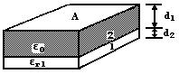
Find the voltage across each dielectric in the capacitor shown in the figure when the applied voltage is V.
System Parameters
Permittivity of free space:
Solution
The capacitances of each region may be found separately:
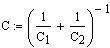
The total capacitance for this system, as shown in the previous problem (Problem 7.2), is
P.19 |
|
P.20 Capacitor Voltage Divider |
|
|
The flux density across the structure will be constant, since the charge on the upper plate is constant.
The electric field in each section is
from which the respective voltage drops are
where
as expected.
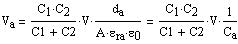
If you examine this procedure closely, you can find a general relation for the voltages in this system. Starting with either electric field,
So, for example
This is known as the capacitor voltage divider for capacitors in series. Can you arrive at the corresponding expression for capacitors in parallel?